
Ford Model T Transmission Model
Fall 2022 - Spring 2024
Eager to get a taste of real world engineering endeavors, I reached out to Johns Hopkins Mechanical Engineering professors. Dr. Stephen Belkoff reached back with a project. He wanted me to design a model of Ford Model T transmission to help him demonstrate the concept of planetary motion to his mechanical engineering undergraduate students.
-
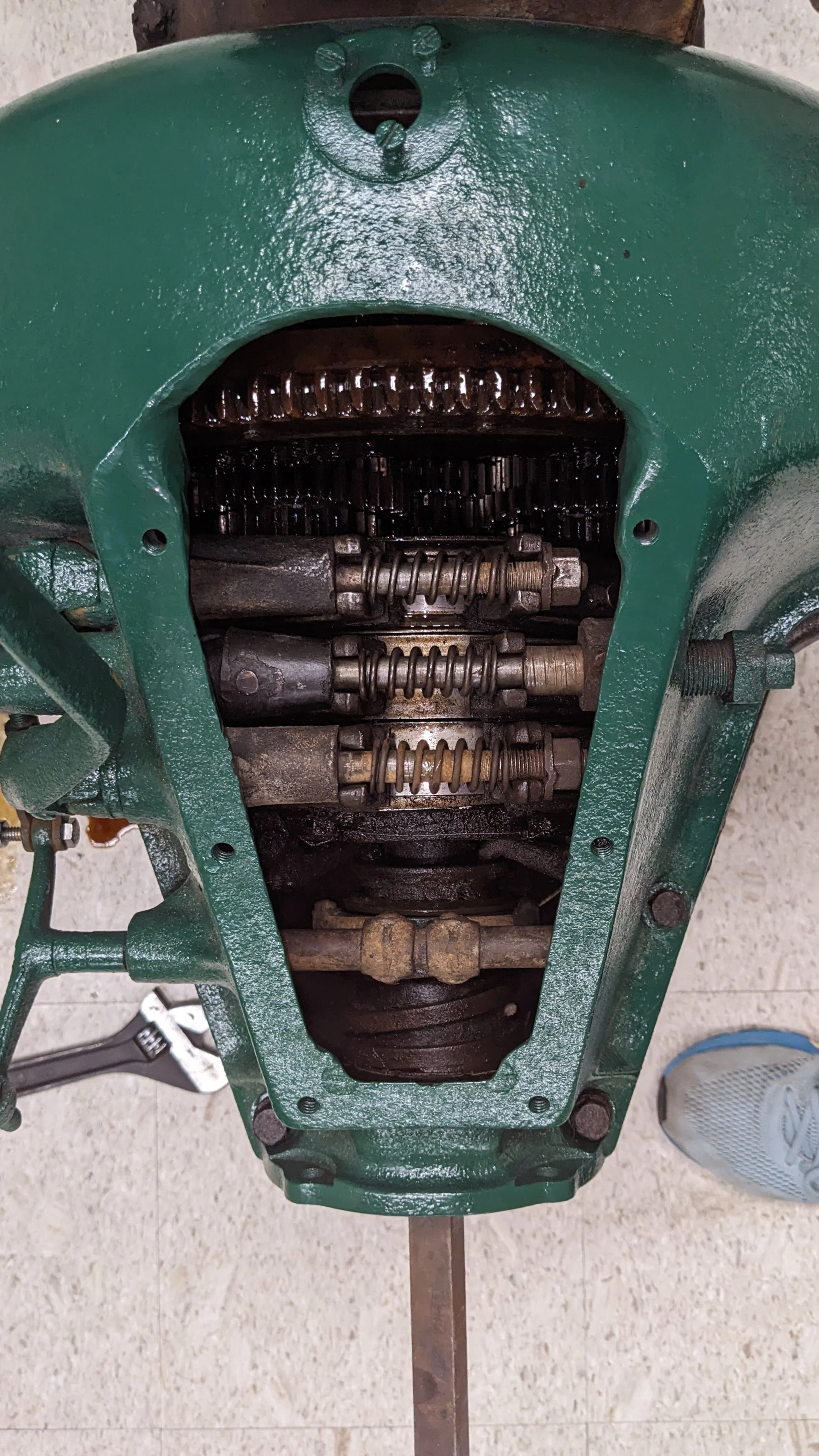
My first step of this project was learning exactly how the transmission worked. This meant talking with Dr. Belkoff and visiting his classroom and lab. The picture is a depiction of a real Ford Model T transmission in Dr. Belkoff’s classroom.
-

After truly understanding how the transmission worked, I began creating sketches in CAD (I used Fusion 360).
-

Here is the CAD of a gear tip that will assemble with the gear drum to form a drum gear.
-

This is a little piece that will connect the planetary gears to the flywheel.
-
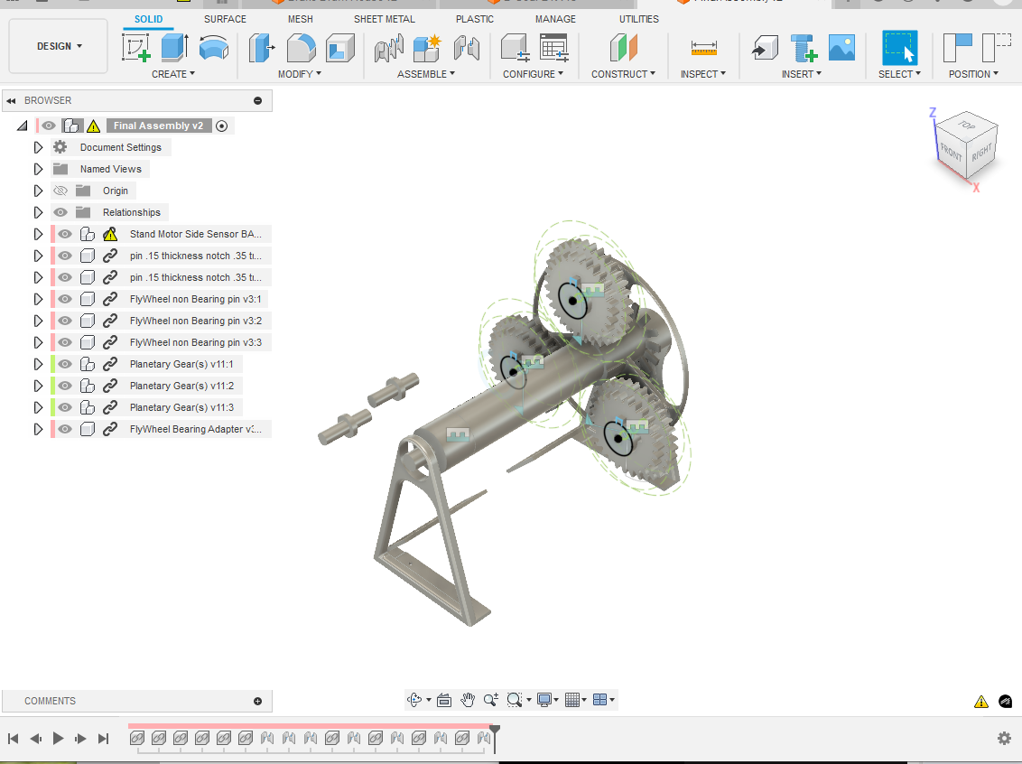
This is an early assembly of the transmission in CAD.
-
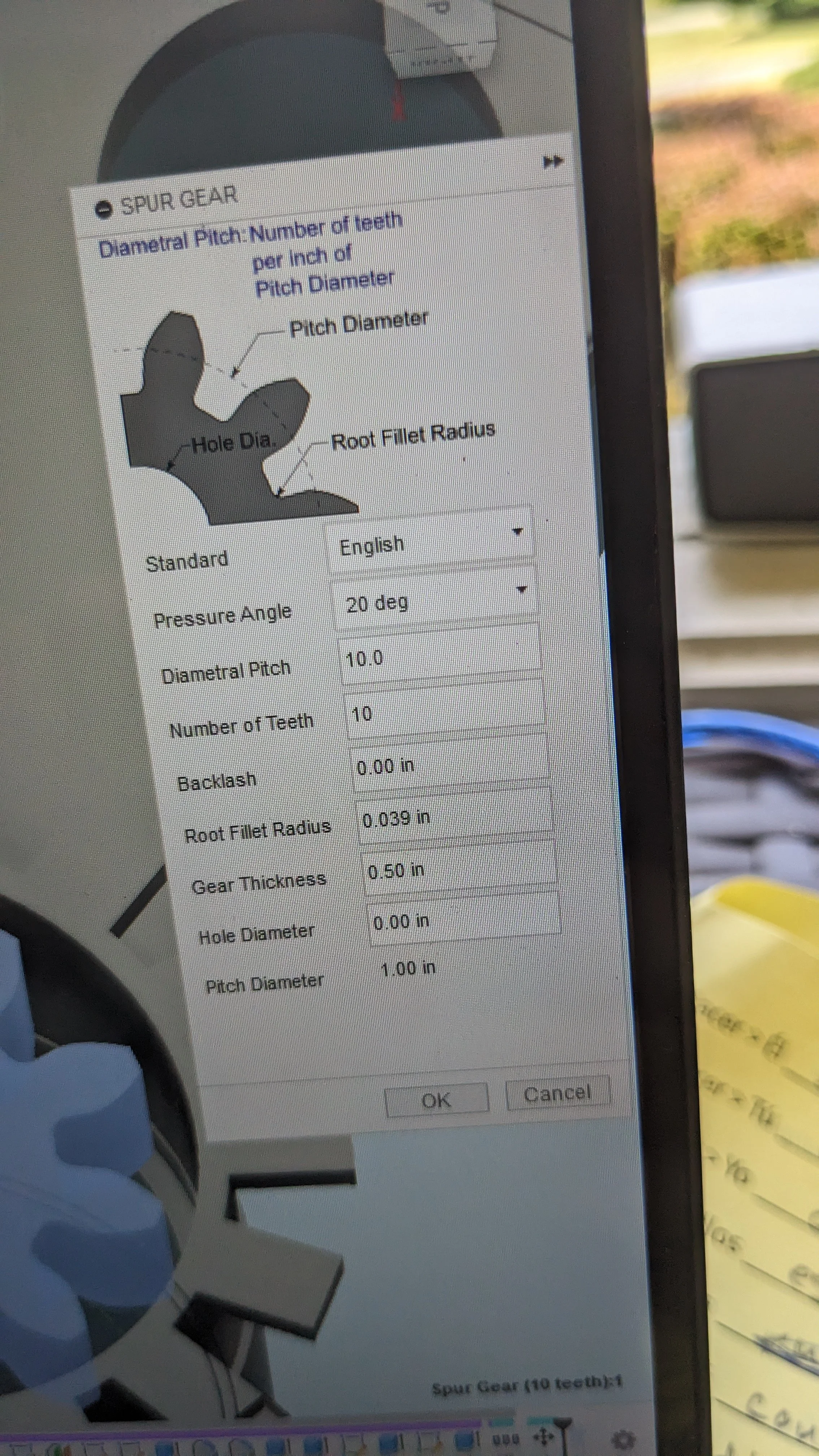
This is a picture of the gear constructor in CAD. All these measures were taken into consideration when designing the gears.
-

This is a picture of the slicer software I used to make 3D printable files out of the CAD files. This software allows me to modify things like printing speed, infill amount, infill pattern, wall thickness of the print, and more.
-

After making some rough CAD designs, I 3D printed some pieces to test the fit.
-

This is some of the pieces put together. The fit in this model was too tight. I made many changes to the CAD sketches to try to fix the fit issues.
-

After making the test pieces I went and redesigned and altered most pieces of the transmission and then 3d printed all the pieces again. Most of the pieces of the transmission are in this picture.
-

I had to slightly sand down these pieces in order for them to fit properly.
-

After printing the pieces and sanding them down, I realized that due to friction between the pieces a method of lubrication would make it work best. The solution I found was creating an oil channel to keep the oil in between the piece and also self distribute the oil.
-

This is the main flywheel and shaft.
-
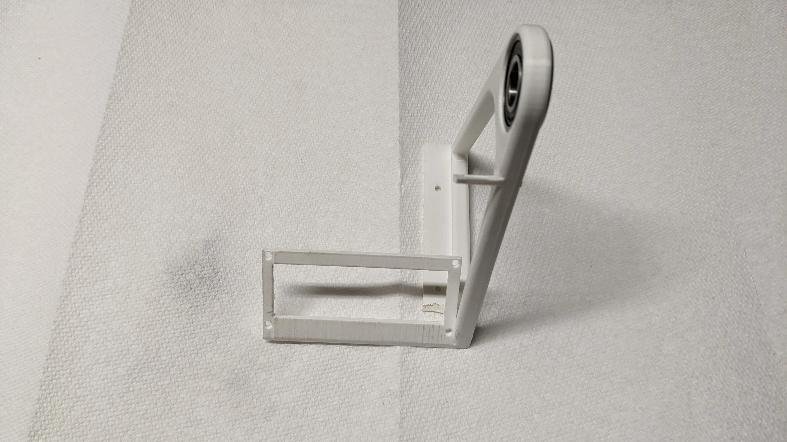
This is a picture of the right stand with a bearing press fitted.
-

These are the three gears assembled. The gear tip pieces were printed separately from the drums and then fitted and glued to form these drum gears.
-

This gear cutout matches and fits perfectly with the gear I made for the motor.
-

This is the gear that the flywheel will sit on to be driven by the motor.
-

These fits in the upper part of the picture are designed to trip the infrared sensors I would later implement to read RPM.
-

This is another angle of the most of the pieces of the transmission put together. The planetary gears seem a little crooked. I purposely added a small amount of play in the piece connecting the planetary gears so that it could self align itself.
-

This is a picture of the transmission fully assembled without any electronics (except the motor).
-

After a lot of work I was finally able to assemble a model of the transmission. Notice how the right stand is slightly taller than the left stand. I did this to counteract the off-center output shaft of the motor.
-

This is the motor I used. The output shaft is off-center so that there would be room inside the motor for gears to allow the motor to produce a lot of torque.
-

After getting the transmission assembled, I began working on the circuit component of the transmission. The first step of building the circuits, I researched Arduino code and basic circuitry.
-

This is an Arduino uno. At this stage I learned about Arudino and coding in that language. At this stage I was troubleshooting the circuits.
-

This is test fitting the electronic components in the 3d printed pieces.
-

This is a rough mock-up of some of the electronic components.
-

I switched to using an Arduino Mega to be able to use more electronic components than I could with the Uno.
-

After getting the circuits to work, I began fitting them to the 3d printed pieces.
-

In order to put all the electronics in an orderly fashion, I modified a box to be able to fit all the electronics in.
-

I drilled holes into the box for the cables.
-

After modifying the box, I placed the electronics in the box.
-

This is a picture of the cables inside the box. I used shrink tubes to keep everything tidy.
-

This is a picture of the Arduino and breadboard. The motor controllers are not in the box.
-

Here is a picture with all of the electronic components. It was a tight fit but I kept everything very neat and tidy.
-

This is a picture of the electronics components in the box with plexiglass cut to fit the top of the box and match up with the screw holes. I added that black tube in the upper left corner of the picture as a stick to press on restart button on the Arduino in case of failure.
-

This is a picture of the transmission almost fully assembled.
-

This is a picture of me fitting the potentiometer to the electronics box.
-

This is the entire transmission assembled. It works!
-

Here is another angle of the transmission. That sensor with the green light is one of the infrared sensors to read the RPM.
-

This is a picture of the infrared sensor on the side with the motor. The tolerance is very small!
-

This is the final iteration of the transmission.
-
