Wrestling Sensor Sleeve
Fall 2024 - Fall 2025
My younger brother suffered a knee injury that caused many matches missed and almost resulted in knee surgery. Having seen firsthand the devastation of injury in wrestling, I researched a way to prevent it. Through my research, I found that there are patterns that predict injury, especially in the knee joint. Learning this, I sought to make a knee sleeve, fitted with sensors, to measure these patterns and predict injury. With this information, wrestlers can take action to prevent the injury from happening.
-

This is a picture of my younger brother’s affected knee.
-

This is another picture of the affect knee (left) next to the normal knee (right).
-

First, I played with an Arduino nano to see if I could utilize it for my purposes. It turns out I needed to download a driver so that I could be able to send code to the Arduino.
-

After researching the types of measurements I will need to be taking, I bought sensors to track this. In this picture there is a temperature sensor and also other Arduino pieces I had from previous projects.
-

Once I was able to send code to the Arduino, I made a program to read angles using a flex sensor.
-

This is a picture of the wiring of the flex sensor circuit.
-

After getting the flex sensor to work, I printed the angle values to the serial monitor.
-

At this point I had started testing and using other sensors.
-

I began trying to get values from an IMU (Inertial measurement unit) to be able to read angles and positions relative to various positions on the knee.
-

Since I need to measure angles and positions relative to each other on the knee, I used 2 IMUs per knee sleeve.
-

This is a picture of the two IMUs wired up to the Arduino nano.
-

After wiring up the two IMUs, I need a way to test them. Here I designed a testing rig. Placing the two IMUs on separate sides of the bendable cardboard allowed me to test different bend angles and positions.
-

This is a picture of my work station at the lab. Here, I was making the testing rig previously explained.
-

This is another picture of me working on the testing rig for the IMUs.
-

This is the wiring for the two IMUs.
-

This is a picture of the testing rig while I was testing the IMUs.
-

Here is a picture of the serial monitor displaying readings of the IMUs.
-

After getting the IMUs, and flex sensor to work, I started playing around with a FSR (force sensitive resistor).
-

This is a picture of the Arduino nano with some wiring.
-

Here is a picture of the readings from the FSR. The data was a little sporadic, I changed the code to fix this bug.
-

After making sure the FSR worked. I added on a temperature sensor (the black cable falling off the desk).
-

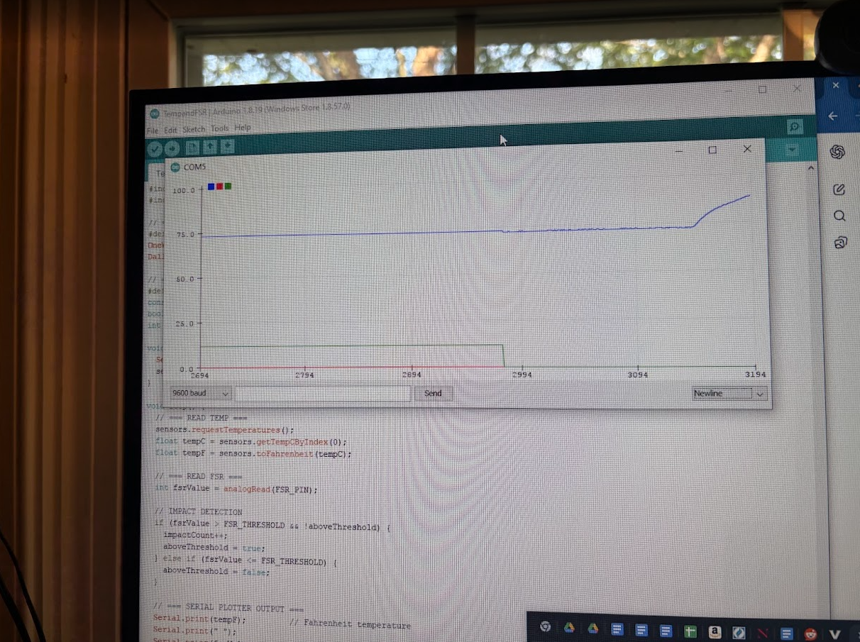
This is a graphical representation of the FSR and temperature sensors. The red spikes represents the impacts the FSR had and the more steady blue line represents the temperature readings. Both were in real time.
-

This is a representation of the temperature and FSR data in the form of a data log. This representation was useful in working out bugs since I could see the exact time impulses were made and when temperature changed.
-
This is a graph of the data collected.
-

After getting the all the sensors to work, I started working on finding a way to secure the electronics to the knee sleeve. I decided to sew a base plate onto the sleeve.
-

This is a closer picture of the base plate assembly. I put tape in the corners so that the thread I was using to sew would not eventually eat through the cardboard-like material I used for the base plate.
-

This is the base plate after I finished sewing it. When I sewed the base plate, I spread out the thread so that the force exerted on the base plate by each individual thread could be spread out, decreasing the chance of the thread eating into the base plate.
-

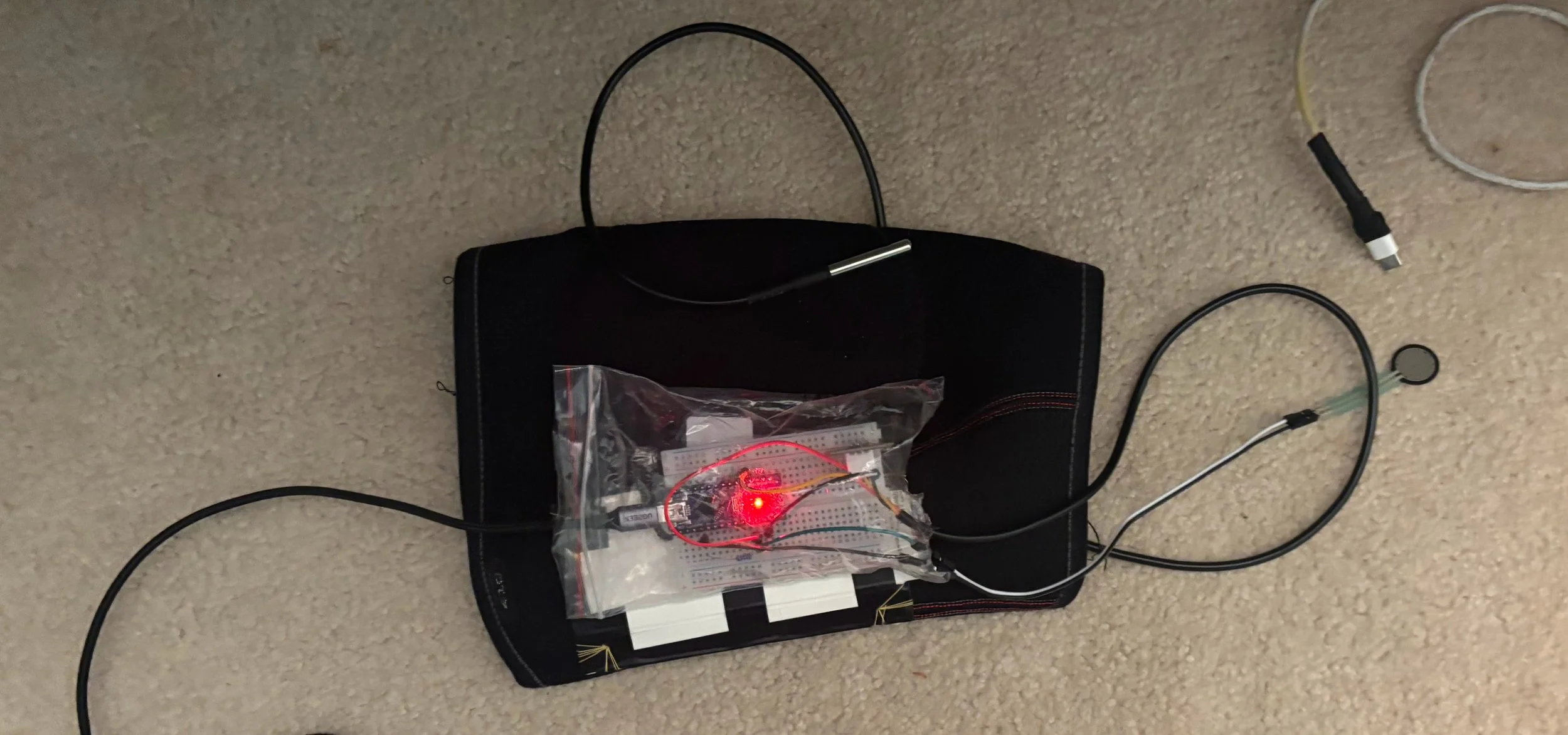
After placing the Arduino and breadboard on the base plate, I surrounded it in a plastic bag to protect it from sweat.
-
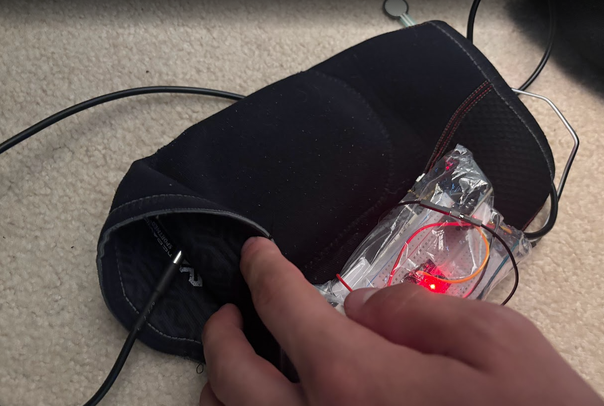
Here is a depiction of how I routed the sensors.